Drilling
Pressure control, circulation, hoisting, pipe handling and well-construction components.
↗ Request a quotation
DRILLING PARTS SUPPLY
EIBAK sources drilling equipment and replacement components against your make, model, duty and documentation requirements.

INTERACTIVE EQUIPMENT MAP / REV 03
Select a labelled component to review its function, the details that shape selection and the information needed for a focused quotation.
Swipe across the diagram to inspect every labelled component.

DRILLING SUPPLY RANGE
Each component page sets out its role, the main selection checks and the information we need to prepare a focused quotation.

The derrick gives the rig the height and strength needed to lift and handle long sections of drill pipe.
Open component file ↗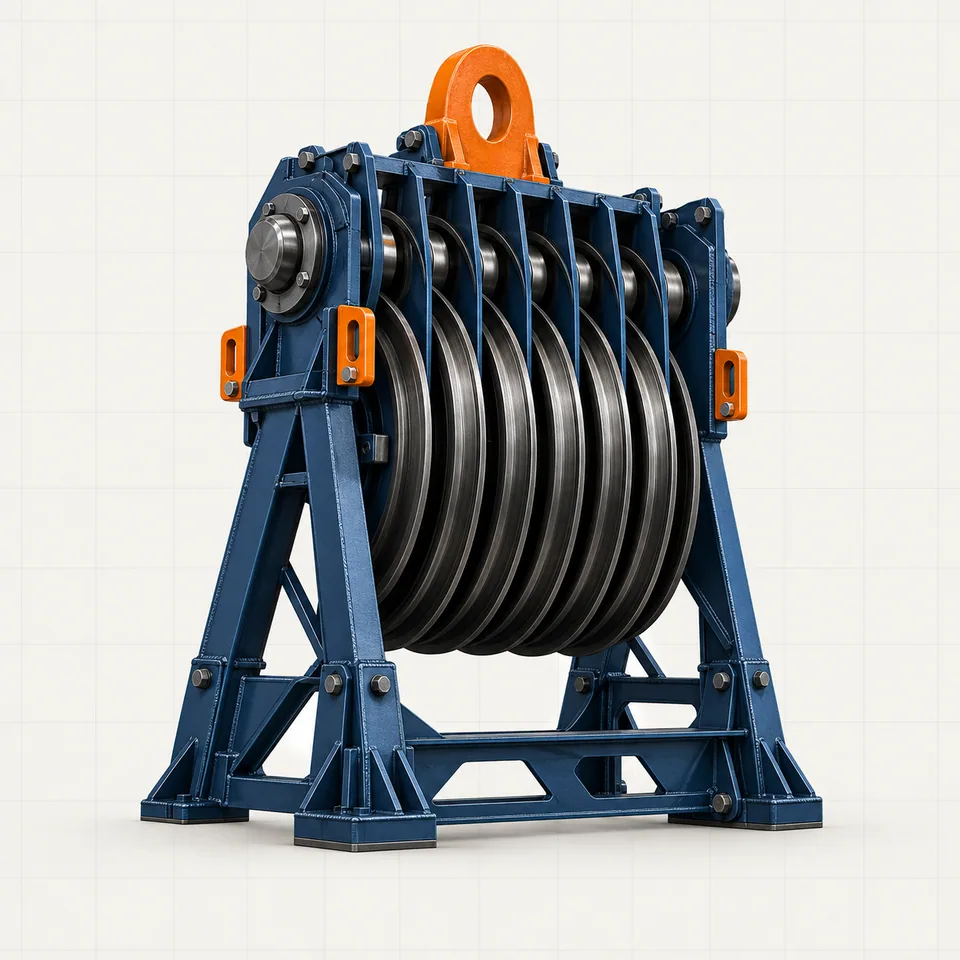
Mounted at the top of the derrick, the crown block guides the drilling line and helps create the lifting power of the hoisting system.
Open component file ↗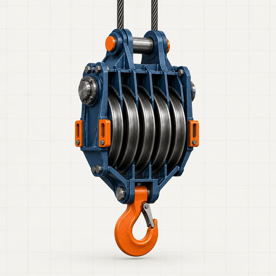
The traveling block moves vertically inside the derrick, carrying the hook and the load suspended below it.
Open component file ↗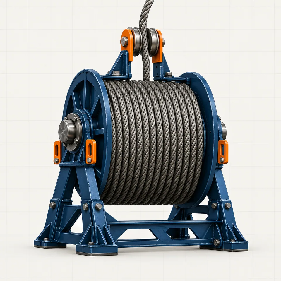
This high-strength wire rope runs between the crown and traveling blocks to raise and lower the drill string.
Open component file ↗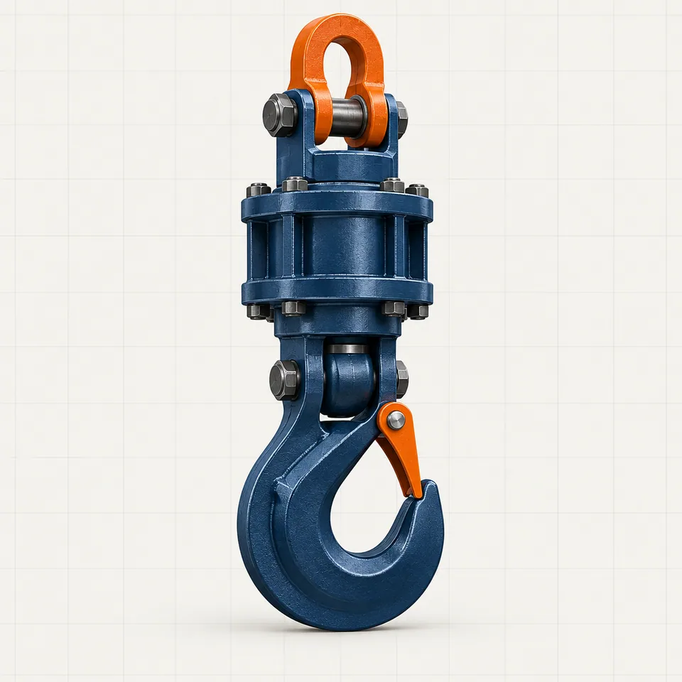
The hook is the heavy-duty connection that carries the swivel, top drive and drill string below the traveling block.
Open component file ↗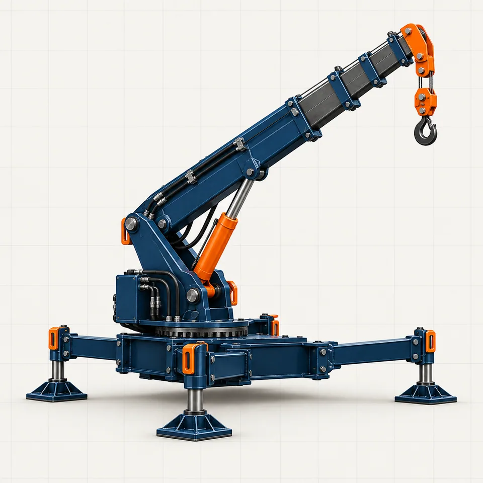
A rig-site crane moves tools, equipment and supplies around the location, outside the main drilling hoist.
Open component file ↗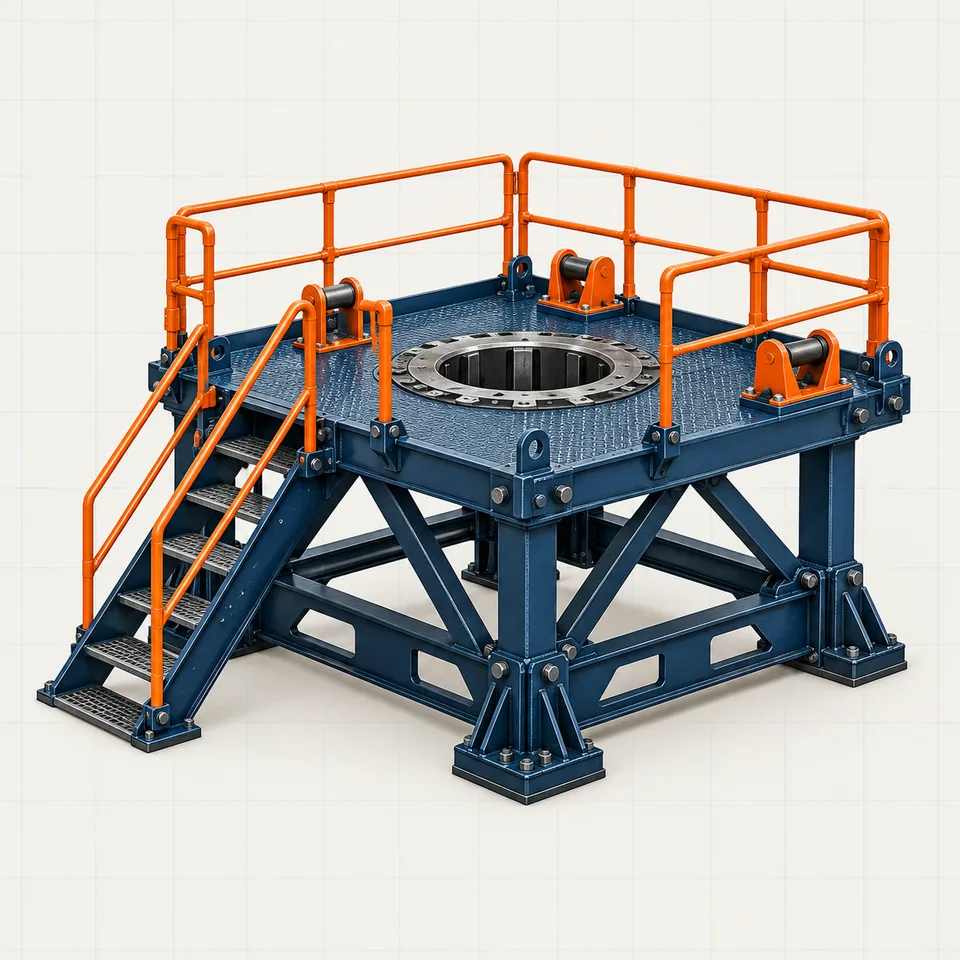
The rig floor is the main working deck where the crew handles pipe and operates equipment above the well center.
Open component file ↗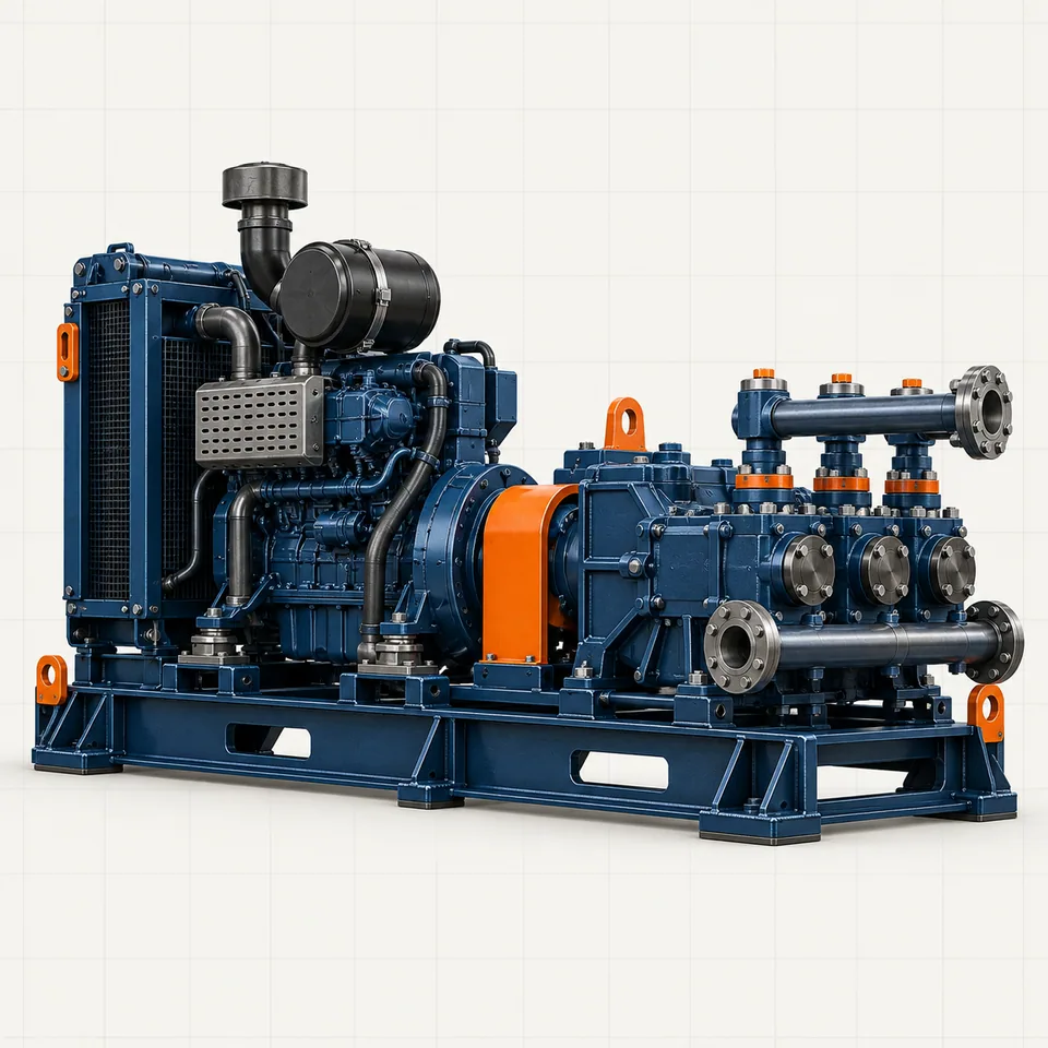
Power units run the rig, while mud pumps move drilling fluid through the high-pressure circulation system.
Open component file ↗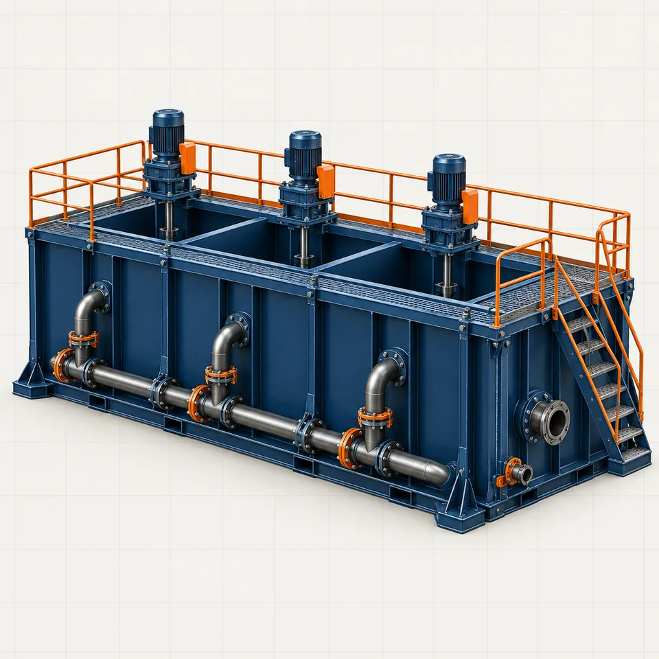
Mud tanks store, mix and condition drilling fluid before it is pumped downhole or returned for treatment.
Open component file ↗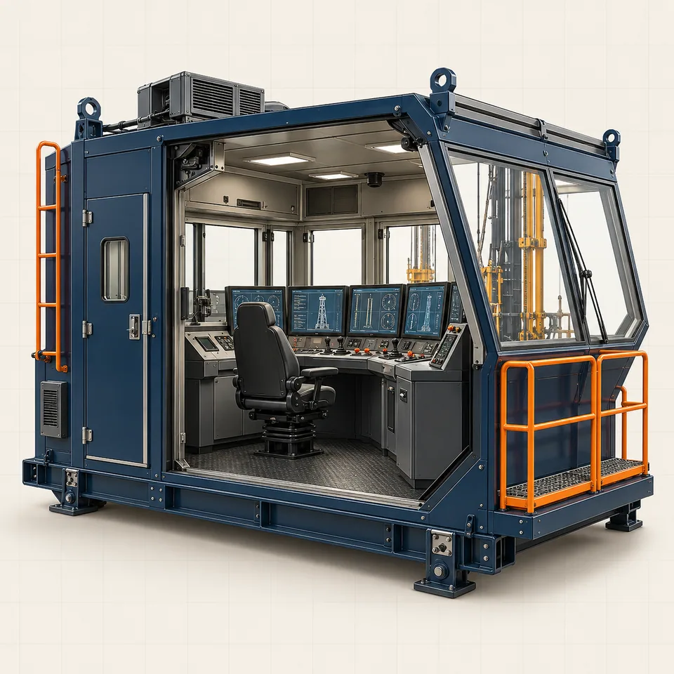
The control room gives the driller a central place to monitor equipment, respond to alarms and coordinate rig operations.
Open component file ↗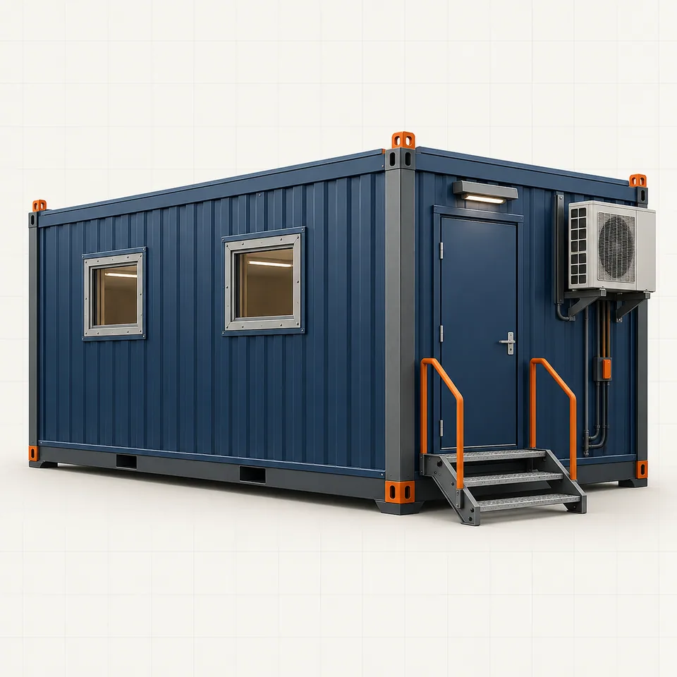
Accommodation modules provide practical living, office and welfare space for crews working at remote drilling locations.
Open component file ↗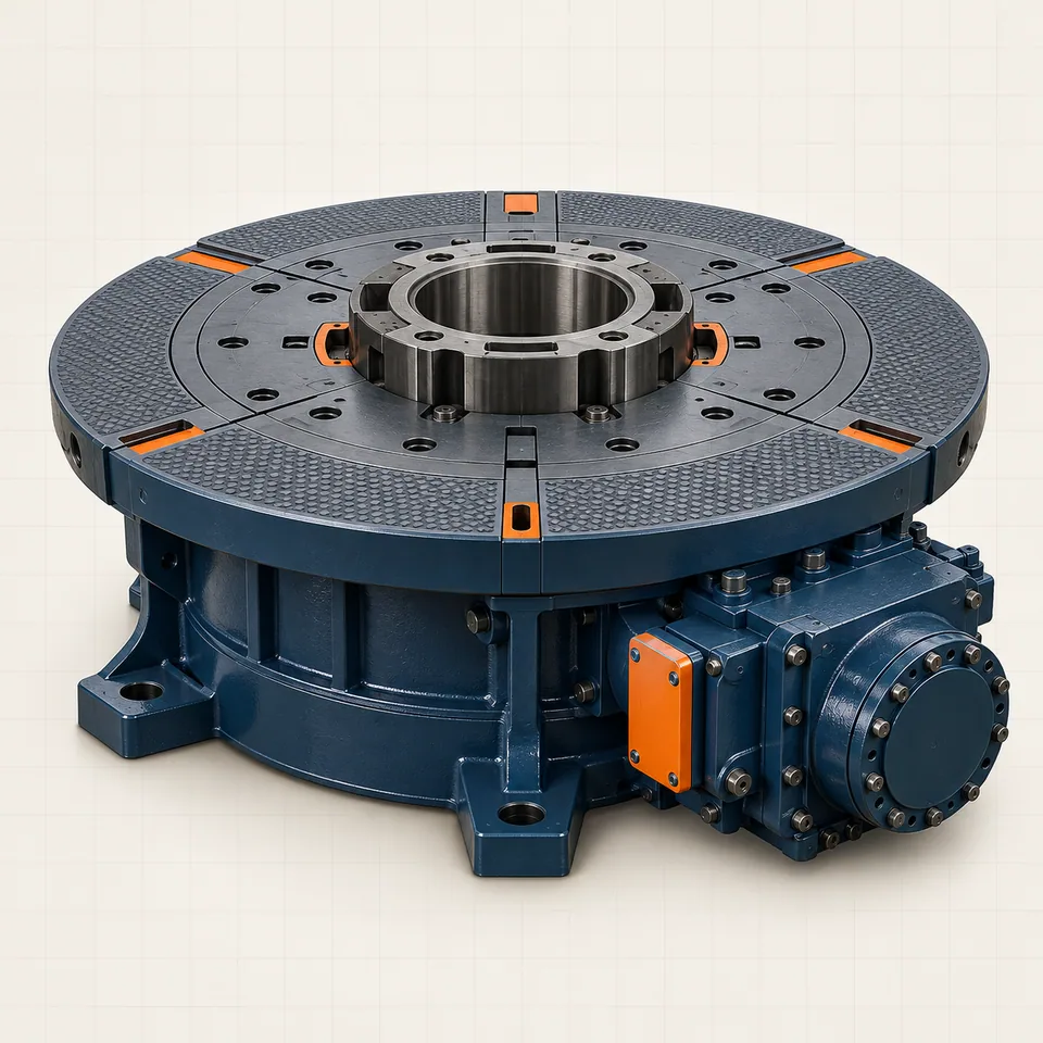
On a conventional rig, the rotary table turns the drill string and provides an opening through the rig floor.
Open component file ↗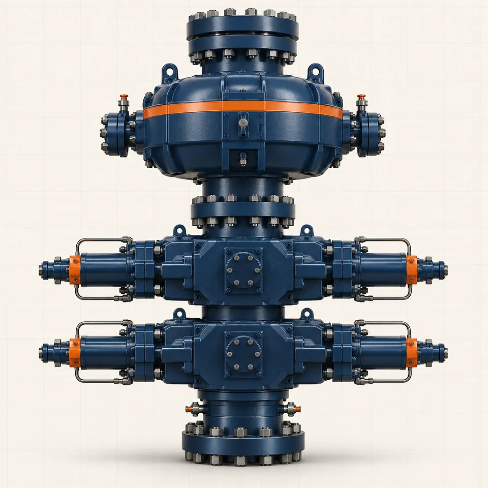
The BOP is a critical well-control assembly used to close around, suspend or shear pipe and help contain unexpected well pressure.
Open component file ↗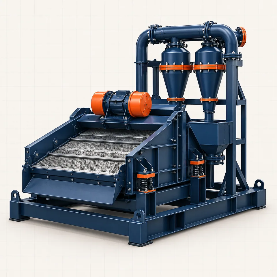
Solids-control equipment removes drilled rock from returning mud so the fluid can be conditioned and reused.
Open component file ↗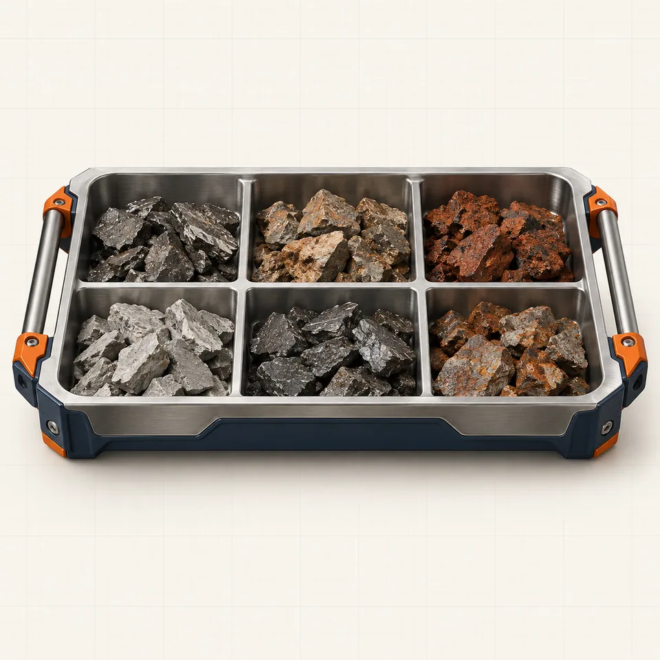
Drill cuttings are fragments of formation created by the bit and carried to surface in the drilling fluid.
Open component file ↗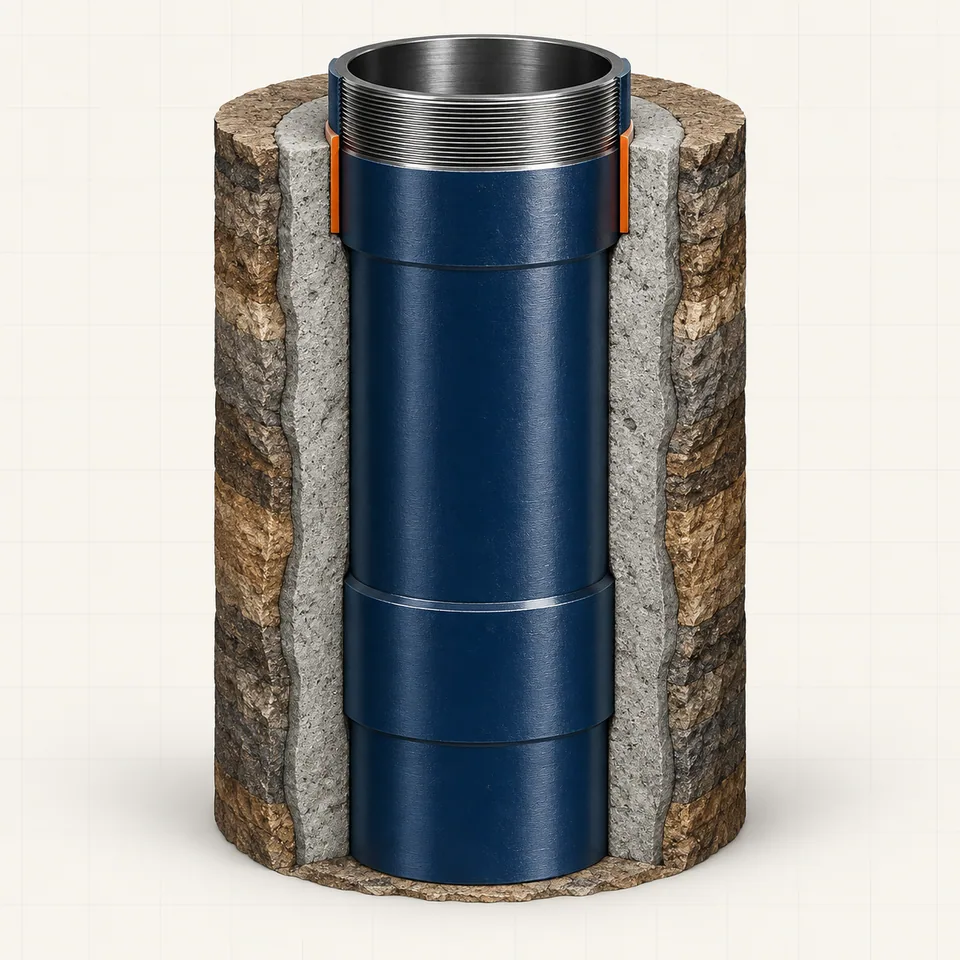
Surface casing stabilizes the shallow wellbore, protects freshwater zones and supports the wellhead and pressure-control equipment.
Open component file ↗
Well cement supports the casing, isolates formations and helps maintain integrity along the annular space.
Open component file ↗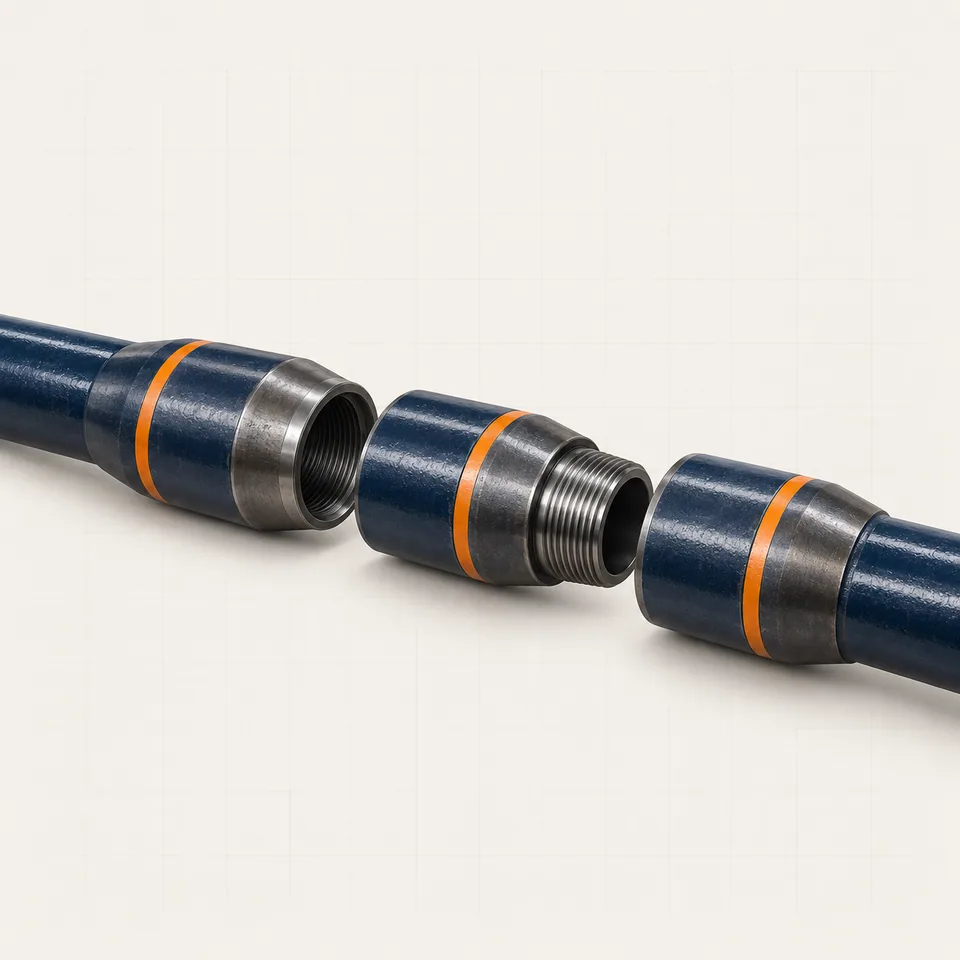
Drill pipe carries torque and drilling fluid between the surface equipment and the bottom-hole assembly.
Open component file ↗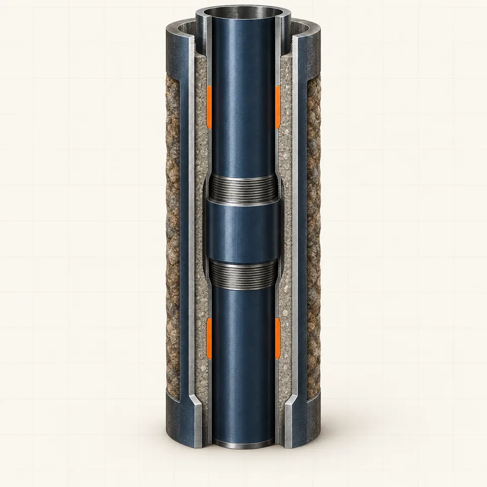
Intermediate casing isolates difficult formations and allows drilling to continue safely below the surface string.
Open component file ↗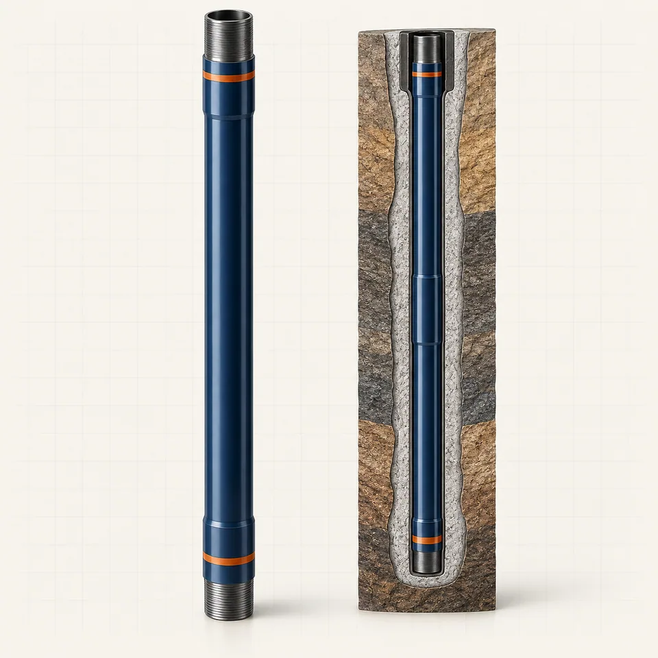
Production casing creates a durable structural and pressure barrier through the deepest part of the well.
Open component file ↗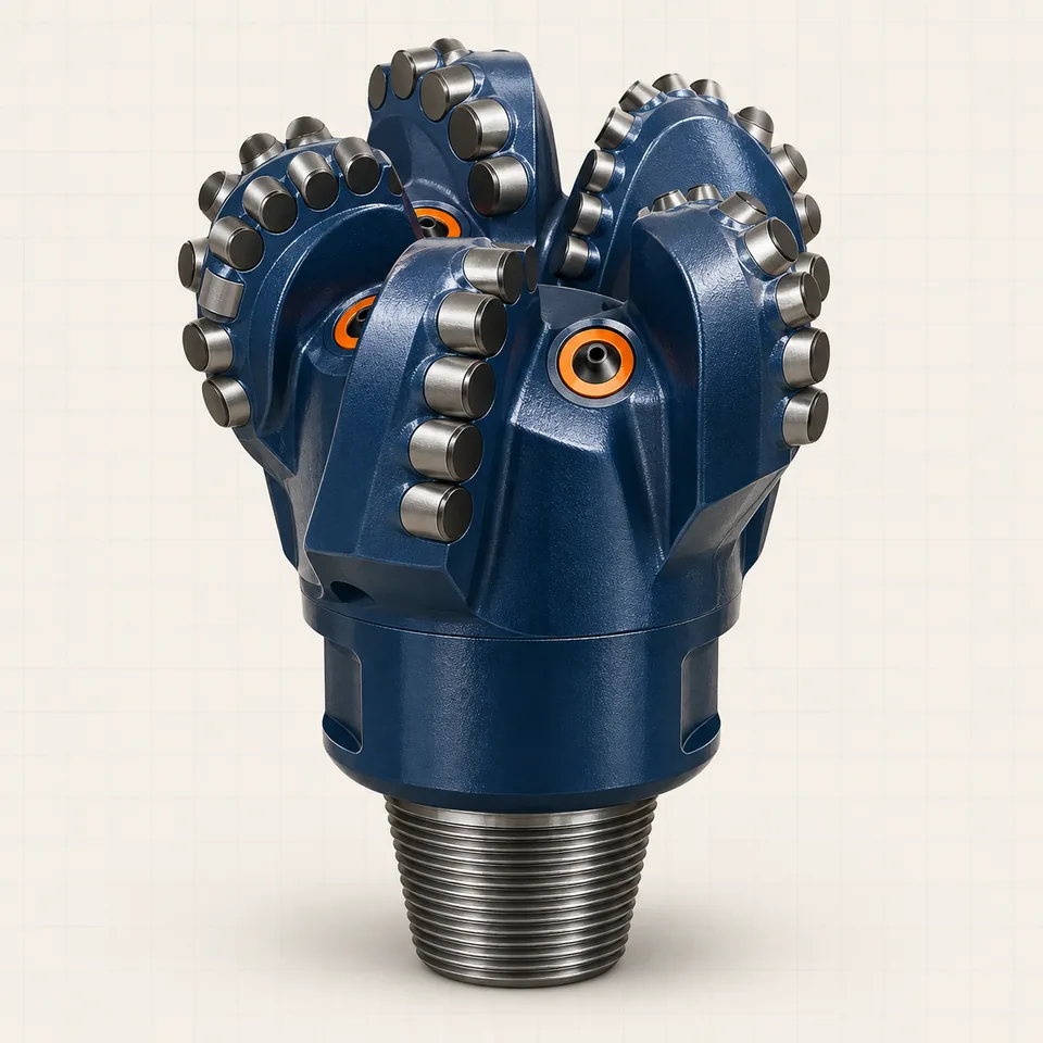
The drill bit cuts the rock at the bottom of the well and turns applied weight and rotation into new hole.
Open component file ↗CAPABILITY RANGE
Drilling leads our work. We apply the same specification-led sourcing process to pipeline, refinery, petrochemical and welding requirements.
Pressure control, circulation, hoisting, pipe handling and well-construction components.
↗Specified components and consumables for construction, maintenance and field operations.
↗Industrial equipment sourcing for process, utilities, shutdowns and maintenance.
↗Coordinated supply for demanding chemical-processing environments.
↗Equipment and consumables matched to procedure, material and service conditions.
↗THE EIBAK METHOD
EIBAK acts as the commercial link between your project team and the supply market. We clarify the requirement, coordinate suitable offers and keep documentation and delivery terms visible throughout the inquiry.
Share manufacturer, model, part number, quantity and operating duty.
We review interfaces, ratings, materials and required documentation.
We coordinate suitable manufacturers and suppliers against the stated requirement.
Commercial terms, inspection documents and delivery conditions are aligned.
START AN RFQ
Int’l Procurement & Business Development Manager